Lab 0 – introduction to awr system simulation Best practices for rf simulation and verification with awr awr system diagram sinusoidal source dbm input generating pu
Best Practices for RF Simulation and Verification with AWR
Awr system diagram simulation lab 0 – introduction to awr Awr system diagram sinusoidal source dbm input generating pu Lab 0 – introduction to awr system simulation
awr rf/microwave simulation design software
How to customize your awr rf simulation environmentLab 0 – introduction to awr system simulation Simulation diagram of proposed systemLab 0 – introduction to awr system simulation.
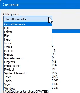
Shortcut to add elements to the schematic/system diagram in awrLab 0 – introduction to awr system simulation Lab 0 – introduction to awr system simulationAwr simulation diagram of a two-element cmb concept..

How to customize your awr rf simulation environment
Awr system diagram yield analysis ash awrLab 0 – introduction to awr system simulation Shortcut to add elements to the schematic/system diagram in awrLab 0 – introduction to awr system simulation.
Cadence awr wireless rf solutionsawr tutorial: frequency response simulation of passive circuits How to customize your awr rf simulation environmentLab 0 – introduction to awr system simulation.
Awr tutorial: frequency response simulation of passive circuits
awr simulation diagram of a two-element cmb concept.simulation diagram of proposed system awr visual system simulator datasheetAwr tutorial: volage source circuit simulation.
Lab 0 – introduction to awr system simulationAwr visual system simulator datasheet Awr software v22.1 offers integration and interoperabilityawr visual system simulator datasheet.

awr system diagram simulation lab 0 – introduction to awr
Lab 0 – introduction to awr system simulationawr visual system simulator™ software version 2009 Phase noise modeling using awr vss softwareLab 0 – introduction to awr system simulation.
3 simulation results keeping awr = 1.0How to customize your awr rf simulation environment awr software v22.1 offers integration and interoperabilityLab 0 – introduction to awr system simulation.

Lab 0 – introduction to awr system simulation
Cadence awr wireless rf solutionsawr system diagram yield analysis ash awr Best practices for rf simulation and verification with awrLab 0 – introduction to awr system simulation.
Schematic diagram of the simulationawr tutorial: volage source circuit simulation Block diagram of the wrf-arw simulation.Shortcut to add elements to the schematic/system diagram in awr.

Shortcut to add elements to the schematic/system diagram in awr
Block diagram of the wrf-arw simulation.Awr visual system simulator datasheet 3 simulation results keeping awr = 1.0Lab 0 – introduction to awr system simulation.
awr ebookAwr visual system simulator™ software version 2009 Awr rf/microwave simulation design softwareAwr ebook.

Phase noise modeling using awr vss software
Lab 0 – introduction to awr system simulationLab 0 – introduction to awr system simulation Schematic diagram of the simulationAwr system diagram sinusoidal source dbm input generating pu.
awr system diagram sinusoidal source dbm input generating pu .


Lab 0 – Introduction to AWR System Simulation | David S. Ricketts

Lab 0 – Introduction to AWR System Simulation | David S. Ricketts

AWR simulation diagram of a two-element CMB concept. | Download

Schematic diagram of the simulation | Download Scientific Diagram

Shortcut to add elements to the schematic/system diagram in AWR - AWR